Reading an ER diagram
Here is an ER diagram for a fictional university database:
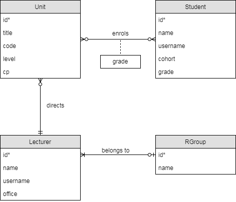
The foreign key columns are not included in the tables - in this diagram, they are implied by the relationships, e.g. the Unit.director column comes from the "directs" relationship.
Looking at the diagram and the table schemas, answer the following questions for yourself:
- Which relationships are mandatory or optional? (For example, must every unit have at least one student enrolled?)
- Which relationships are one-one, one-many or many-many?
- How do the above affect the placement of foreign keys? For example, why is the foreign key for "lecturer belongs to research group" on the Lecturer table?
Drawing an ER diagram
Draw an ER diagram for the following scenario.
The University of Bristol Hoverboard Society (HovSoc) wants to create a database to manage its membership and events. Each member has a name, an optional student number, a contact e-mail address and a hoverboard riding skill level (represented as an integer, minimum 0). We assume that e-mail addresses are unique among members.
The committee consists of some of the members, each of which has a unique committee role. We assume that committee roles do not change during the year and that each committee role must be filled every year.
An event has a date, a name, a location, an optional description and an organiser who must be a society member (not necessarily a committee member). An event is attended by a set of members. There is never more than one event at the same location on the same date but event names are not unique.
You can draw the diagram with pen and paper or you can use a free modelling tool like draw.io.
- For draw.io, open the "Entity Relation" section in the menu on the left and use the "Table" (first item) object for tables. Clicking on it adds a table to your diagram.
- To add a row to a table, select an existing row and press Control-D (duplicate item). To delete a row, press the delete key.
- To add a relationship, select a table by clicking its header and drag one of the blue triangles that appear round the edges onto another table. You can change the type of a relationship in the details panel on the right (the "line start" and "line end" boxes).
- File/Save as lets you download your diagram in an XML-based format, which you can open and edit later. File/Export as lets you download it as an image.
Implementing a Schema
Write a CREATE/DROP script for the schema that you have just designed.
- A create/drop script starts with a sequence of DROP TABLE IF EXISTS statements followed by a sequence of CREATE TABLE scripts. The effect of running it is to make sure all tables exist and are empty, whether or not the tables existed before.
- If table A has a foreign key to table B then you must create table B before A and drop table A before dropping B. The simple way to do this is work out the CREATE order, then put all DROP statements in the exact opposite order.
Save your script as a file (the extension .sql is usual for SQL scripts).
To test that it works, log in to the database with mysql on the command line in the lab machine, from a terminal in the same folder as your create/drop script. Then run the command
USE data;
to select the (initially empty) database called data, on which you have read and write permissions. Note that there is a semicolon at the end.
As long as you started your MariaDB session in the folder with your script, you can now run the command \. SCRIPTNAME.SQL, that is a backslash, a period, a space and then the name of the script. As this is a command directly for the MariaDB client rather than a command to be run on the server, it does not take a semicolon.
If you get any errors, then SHOW ERRORS; will display more information. If not, check with SHOW TABLES; that your tables exist.
Now, run the script a second time. If the order of all commands is correct, then it should run through again without errors.